
Customer: Cybenetics LTD
Syrou 6, Latsia, 2231, Nicosia Cyprus
Syrou 6, Latsia, 2231, Nicosia Cyprus

Pure Power 13 M 550W
| Electronic Loads | Chroma 63601-5 x2 Chroma 63600-2 Chroma 63640-80-80 x10 Chroma 63610-80-20 |
| AC Sources | Chroma 6530, APM SP300VAC4000W-P, GW Instek ASR-3500 |
| Power Analyzers | Rohde & Schwarz HMC8015 & NPA701 |
| Oscilloscopes | Picoscope 4444, Siglent SDS2104X PLUS |
| Sound Analyzer | Bruel & Kjaer 2270 G4 |
| Microphone | Bruel & Kjaer Type 4955-A |
| Temperature Logger | Picoscope TC-08 |
| Tachometer | UNI-T UT372 |
| Multimeters | Keysight 34465A |
| EMI Analyzer | TekBox TBMR-110M-EU |
| Isolation Transformer | 4kVA |
| UPS | FSP Champ Tower 3kVA, CyberPower OLS3000E 3kVA |
| Testing Methodology | Cybenetics PSU Test Protocol |
| Voltage | 115V | 230V |
|---|---|---|
| Efficiency (>1450 Load Combinations) | 90.603% | 92.463% |
| Efficiency Graphs | 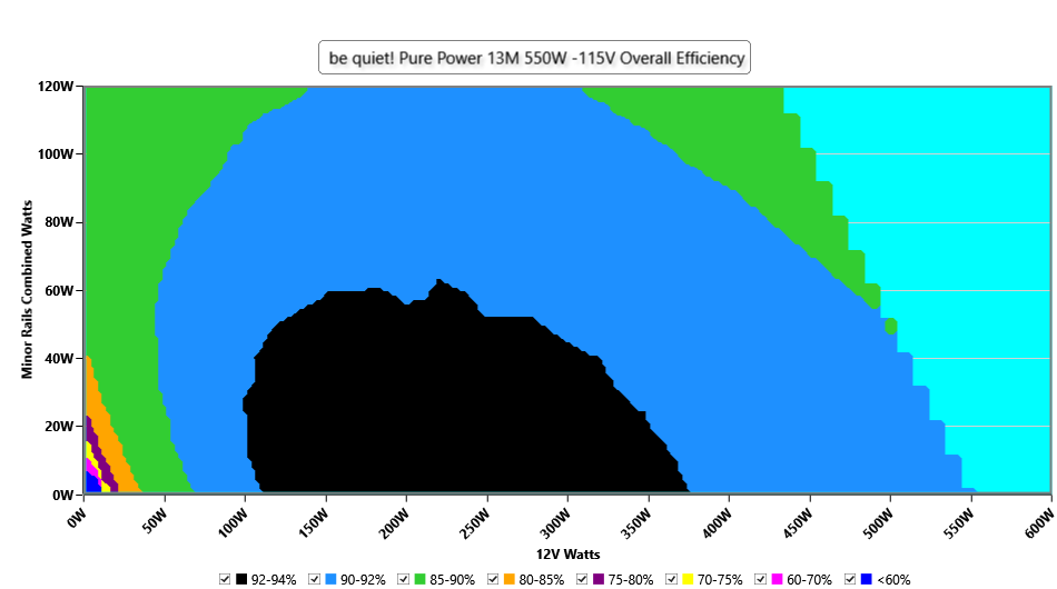 | 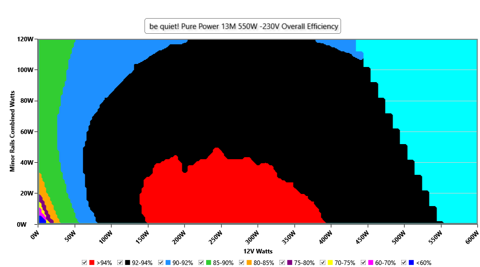 |
| Average PF (>1450 Load Combinations) | 0.987 | 0.957 |
| 12V Step | - | |
| 5V/3.3V Step | - | |
| Standby Power Consumption | 0.0434W | 0.1319W |
| ErP Lot 3/6 Ready | ✓ | |
| (EU) No 617/2013 Compliance | ✓ | |
| Average Efficiency VSB | 85.813% | 83.580% |
| Voltage | 115V | 230V |
|---|---|---|
| Noise Rating (>1450 Load Combinations) | 6.00dBA | 6.00dBA |
| Noise Graphs | 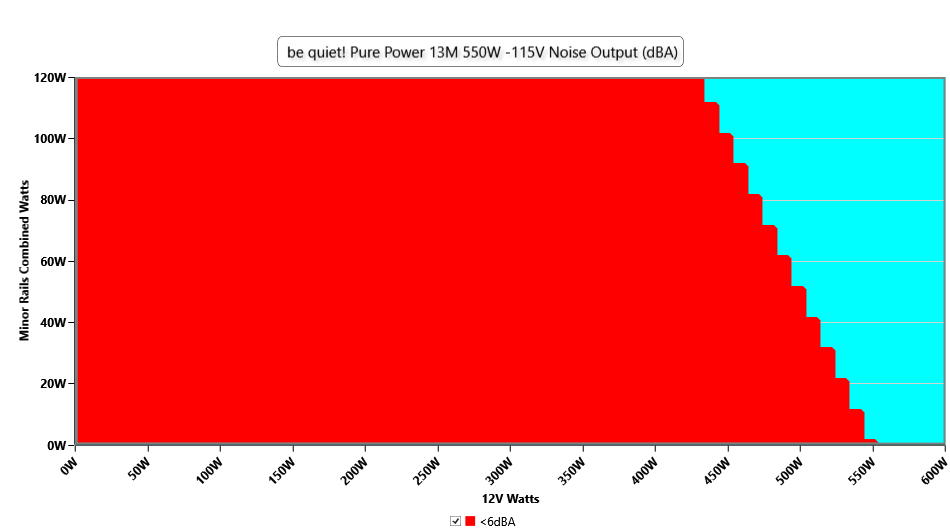 | 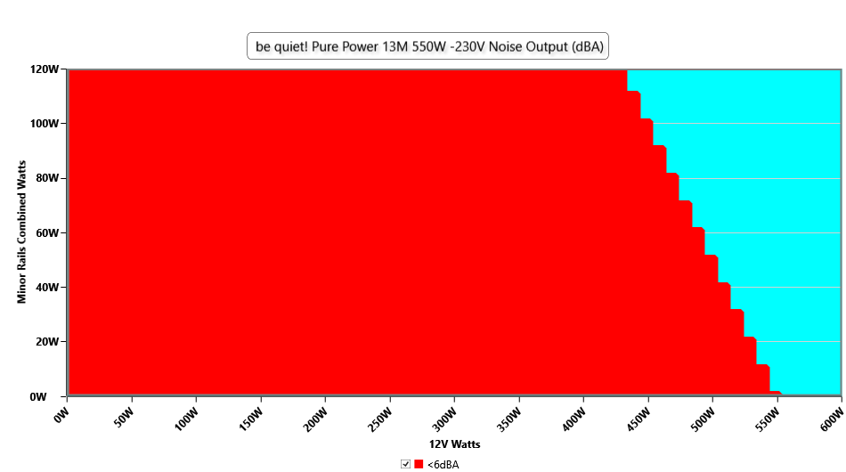 |
| Efficiency With 10W (≤500W) or 2% (>500W) Load | 69.680% |
| Hold Up Time | 25.30ms |
| Power OK | 23.40ms |
| Power OK to DC Loss | 1.90ms |
| Test\Rail | +12V | 5V | 3.3V | 5VSB |
| 100ms | 12.027 | 4.997 | 3.281 | 5.038 |
| 10ms | 11.898 | 4.984 | 3.265 | 5.022 |
| 1ms | 11.836 | 4.973 | 3.254 | 5.015 |
| 0.1ms | 11.765 | 4.962 | 3.242 | 5.020 |
| Product Identification Details | |
| Brand | be quiet! |
| Model | Pure Power 13 M 550W |
| OEM | FSP |
| Serial Number | EUS5081000876 |
| Product Specifications | |
| Manufacturer | |
| Rated Voltage (Vrms) | 100-240 |
| Rated Current (Arms) | 5-10 |
| Rated Frequency (Hz) | 50-60 |
| Rated Power (W) | 550 |
| Operating Temperature (Continuous Full Load) (°C) | |
| Type | ATX12V |
| Cable Design | Fully Modular |
| Warranty | |
| Cybenetics | |
| Dimensions (W x H x D) | |
| Weight | |
| Cooling | 120mm Rifle Bearing Fan (BQ QF2-12025-LS) |
| Semi-Passive Operation | ✓ |
| Cybenetics Testing Information | |
| Lab ID | BQ55002851 |
| Date of receipt | May 9, 2025 |
| Testing Date | Jun 16, 2025 |
| Report Issued Date | Jun 18, 2025 |
| Engineer Name | - |
| Authorized By the Laboratory Technical Manager | Aristeidis Bitziopoulos |
| Signature |  |
| Modular Cables | ||||
| Description | Cable Count | Connector Count (Total) | Gauge | In Cable Capacitors |
| ATX connector 24 pin (550mm) | 1 | 1 | 18-22AWG | No |
| 4+4 pin EPS12V (650mm) | 1 | 1 | 18AWG | No |
| 2x 6+2 pin PCIe (500mm) | 2 | 2 | 18AWG | No |
| 12+4 pin PCIe (600mm) (300W) | 1 | 1 | 16-28AWG | No |
| SATA (500mm+150mm+150mm) | 1 | 3 | 16-28AWG | No |
| SATA (510mm+150mm) / 4-pin Molex (+150mm+145mm) | 1 | 2 / 2 | 18AWG | No |
| AC Power Cord (1350mm) - C13 Coupler | 1 | 1 | 18AWG | - |
| Over Voltage Protection | ✓ |
| Under Voltage Protection | ✓ |
| Over Power Protection | ✓ |
| Over Current (+12V) Protection | ✓ |
| Over Temperature Protection | ✓ |
| Short Circuit Protection | ✓ |
| Surge Protection | ✓ |
| General Data | |
| Manufacturer (OEM) | FSP |
| PCB Type | Double-Sided |
| Primary Side | |
| Transient Filter | 4x Y caps, 2x X caps, 2x CM chokes, 1x MOV |
| Inrush Protection | NTC Thermistor SCK085A & Relay |
| Bridge Rectifier(s) | 2x Yangjie GBJ1508 (800V, 15A @ 87°C) |
| APFC MOSFETs | 2x STMicroelectronics STF18N60M2 (650V, 8A @ 100°C, Rds(on): 0.280Ohm) |
| APFC Boost Diode | 1x DSC06C065 (650V, 6A @ 25°C) |
| Bulk Cap(s) | 2x Elite (420V, 270uF each or 540uF combined, 3000h @ 85°C, GSF(M)) |
| Main Switchers | 2x Toshiba TK12A60W (600V, 11.5A @ 25°C, Rds(on): 0.3Ohm) |
| IC Driver | Novosense NSI6602 |
| APFC Controller | Champion CM6500UNX |
| Resonant Controller | Champion CM6901X |
| Topology |
|
| Secondary Side | |
| +12V MOSFETs | 4x CMR024N04NS |
| 5V & 3.3V | DC-DC Converters: 4x Nexperia PSMN3RO-30YLD (30V, 100A @ 25°C, Rds(on): 3.1mOhm) PWM Controller(s): ANPEC APW7159C |
| Filtering Capacitors | Electrolytic: 3x Elite (2,000 @ 105°C, EL) 2x Elite (2-5,000 @ 105°C, ED) 1x Elite (4-10,000 @ 105°C, EY) 2x Elite (3-6,000 @ 105°C, EV) Polymer: 19x Apaq, 8 Elite (CS), 9x Biostar |
| Supervisor IC | IN1S4241-SDG (OCP, OVP, UVP, SCP, PG) |
| Fan Controller | Grenergy GR8031 |
| Fan Model | BQ QF2-12025-LS (120mm, 12V, 0.12A, Rifle Bearing Fan) |
| 5VSB Circuit | |
| Synchronous Rectification Driver | Leadtrend LD8926AA13 Synchronous Rectification IC |
| Photos | 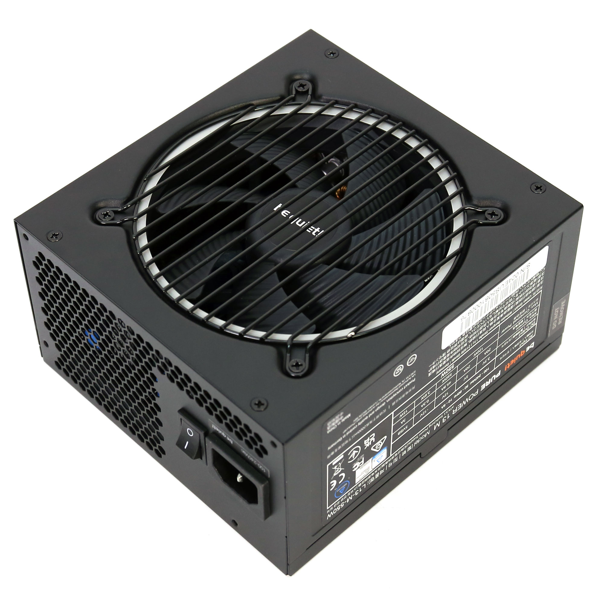 | 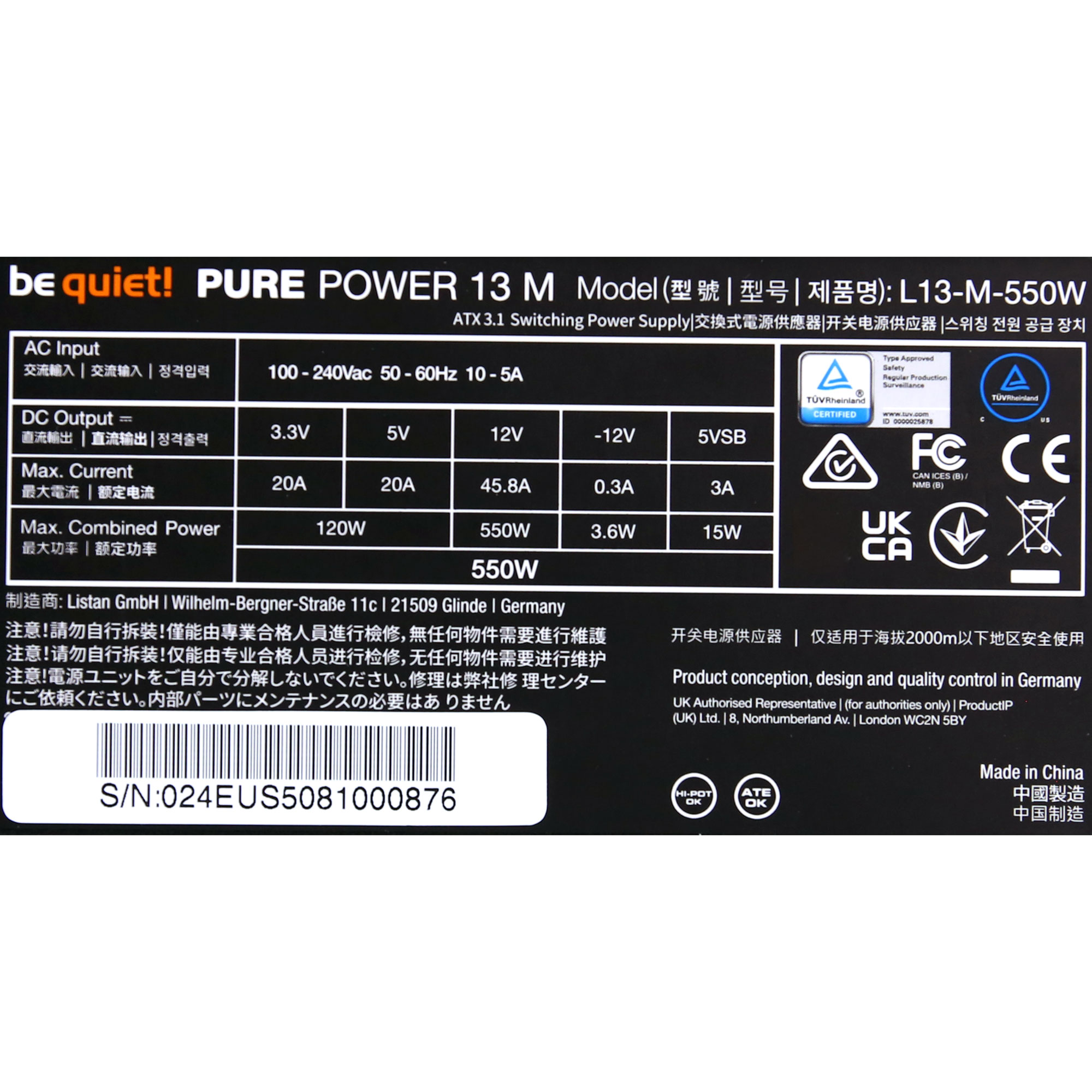 |
| Top side | Power specifications label |
F.1 General Statement
Measurement uncertainty associated with the reported results was evaluated and estimated in accordance with JCGM 100:2008 (Guide to the Expression of Uncertainty in Measurement — GUM) and ISO/IEC 17025:2017, Clauses 7.6 and 7.2.
The uncertainty budget accounts for all significant identified contributors arising from the measurement process, instrumentation, test conditions, and operator interaction.
The reported expanded uncertainty U is obtained by multiplying the combined standard uncertainty uc by a coverage factor k = 2, corresponding to a confidence level of approximately 95 %, assuming a normal probability distribution.
Unless otherwise stated, the reported uncertainty applies only to the specific measurements performed and does not include long-term drift, aging effects, or future environmental changes.
F.2 Expanded Measurement Uncertainty by Measurement Type
| Measurement | Expanded Uncertainty U (k=2, norm) |
| Efficiency | ±0.18% |
| Timings | ±0.48ms |
| Power Excursions (Transient Response) | ±0.1V |
| Conducted EMI Emissions (150 kHz – 30 MHz) | ±2.35 dBμV |
| Noise Output | ±1.23 dB |