
Customer: -
Everdenberg 117,47100 Bayside Parkway Fremont, CA 94538,USA.
Everdenberg 117,47100 Bayside Parkway Fremont, CA 94538,USA.

RM1000x Shift (ATX v3.0)
| Electronic Loads | Chroma 63601-5 x2 Chroma 63600-2 Chroma 63640-80-80 x10 Chroma 63610-80-20 |
| AC Sources | Chroma 6530, APM SP300VAC4000W-P, GW Instek ASR-3500 |
| Power Analyzers | Rohde & Schwarz HMC8015, Rohde & Schwarz NPA701 |
| Oscilloscopes | Picoscope 4444, Siglent SDS2104X PLUS |
| Sound Analyzer | Bruel & Kjaer 2270 G4 |
| Microphone | Bruel & Kjaer Type 4955-A |
| Temperature Logger |
Picoscope TC-08 |
| Tachometer | UNI-T UT372 |
| Multimeters | Keysight 34465A |
| EMI Analyzer | TekBox TBMR-110M-EU |
| Isolation Transformer | 4kVA |
| UPS | FSP Champ Tower 3kVA, CyberPower OLS3000E 3kVA | Testing Methodology | Cybenetics PSU Test Protocol |
| Voltage | 115V | 230V |
|---|---|---|
| Efficiency (>1450 Load Combinations) | 88.494% | 90.176% |
| Efficiency Graphs | 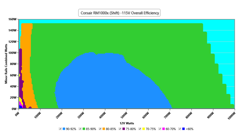 | 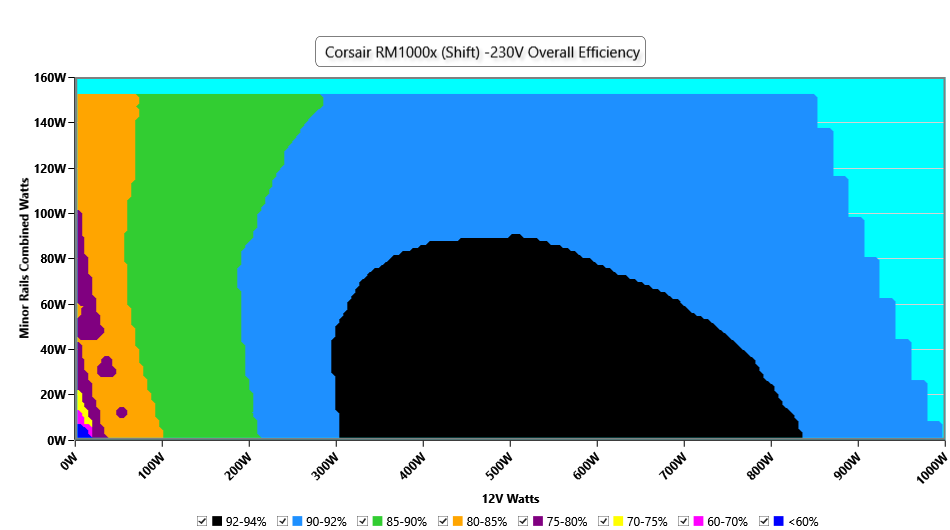 |
| Average PF (>1450 Load Combinations) | 0.991 | 0.970 |
| Standby Power Consumption | 0.0170W | 0.0807W |
| ErP Lot 3/6 Ready | ✓ | |
| (EU) No 617/2013 Compliance | ✓ | |
| Average Efficiency VSB | 76.997% | 78.295% |
| Voltage | 115V | 230V |
|---|---|---|
| Noise Rating (>1450 Load Combinations) | 23.62dBA | 23.59dBA |
| Noise Graphs | 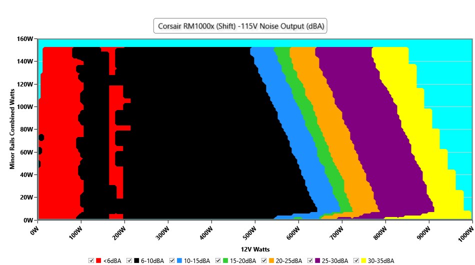 | 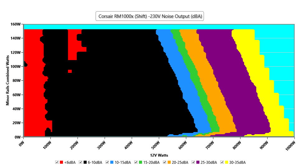 |
| Efficiency With 10W (≤500W) or 2% (>500W) Load | 76.523 |
| Hold Up Time | 24.00 |
| Power OK | 21.00 |
| Power OK to DC Loss | 3.00 |
| Model Name | Corsair |
| Lab ID | CR10002031 |
| Serial Number | 22177118000051920187 |
| Date of receipt | Jun 10, 2022 |
| Testing Date | Jun 22, 2022 |
| Report Issued Date | Jun 22, 2022 |
| DUT Notes | 2031 |
| Engineer Name | |
| Authorized By the Laboratory General Manager | Aristeidis Bitziopoulos |
| Signature |  |
| Modular Cables | ||||
| Description | Cable Count | Connector Count (Total) | Gauge | In Cable Capacitors |
| ATX connector 20+4 pin (610mm) | 1 | 1 | 16-18AWG | No |
| 4+4 pin EPS12V (650mm) | 2 | 2 | 18AWG | No |
| 12 pin PCIe (660mm) | 1 | 1 | 16AWG | No |
| 6+2 pin PCIe (660mm) | 3 | 3 | 16AWG | No |
| 6+2 pin PCIe (660mm+100mm) | 2 | 4 | 16-18AWG | No |
| SATA (460mm+110mm+110mm+110mm) | 4 | 16 | 18AWG | No |
| 4 pin Molex (450mm+100mm+100mm+100mm) | 2 | 8 | 18AWG | No |
| AC Power Cord (1400mm) - C13 coupler | 1 | 1 | 16AWG | - |
| General Data | - |
| Manufacturer (OEM) | CWT |
| PCB Type | Double Sided |
| Primary Side | - |
| Transient Filter | 6x Y caps, 2x X caps, 2x CM chokes, 1x MOV |
| Inrush Protection | 1x NTC Thermistor SCK20150 (15 Ohm) & Relay |
| Bridge Rectifier(s) | 2x GBJ2506 (600V, 25A @ 100°C) |
| APFC MOSFETs | 3x Infineon IPA60R125P6 (600V, 19A @ 100°C, Rds(on): 0.125Ohm) & 1x Sync Power SPN5003 FET (for reduced no-load consumption) |
| APFC Boost Diode | 1x On Semiconductor FFSP1065A (650V, 10A @ 152°C) |
| Bulk Cap(s) | 1x Nippon Chemi-Con (400V, 560uF, 2,000h @ 105°C, KMR) & 1x Nippon Chemi-Con (400V, 470uF, 2,000h @ 105°C, KMW) |
| Main Switchers | 4x Infineon IPA60R190P6 (600V, 12.7A @ 100°C, Rds(on): 0.19Ohm) |
| Driver IC(s) | Champion CM6500UN |
| Digital Controllers | Champion CU6901VAC |
| Topology | Primary side: APFC, Full-bridge & LLC converter Secondary side: Synchronous Rectification & DC-DC converters |
| Secondary Side | - |
| +12V MOSFETs | 6x Infineon BSC014N06NS (60V, 152A @ 100°C, Rds(on): 1.45mOhm) |
| 5V & 3.3V | DC-DC Converters: 4x UBIQ QN3107M6N (30V, 70A @ 100°C, Rds(on): 2.6mOhm) PWM Controllers: UPI-Semi uP3861P |
| Filtering Capacitors | Electrolytic: 4x Nichicon (2–5,000h @ 105°C, HD), 1x Nichicon (5-6,000h @ 105°C, HV), 1x Nippon Chemi-Con (1-5,000h @ 105°C, KZE), 1x Nippon Chemi-Con (4-10,000h @ 105°C, KYA) 4x Nichicon (4-10,000h @ 105°C, HE) Polymer: 28x FPCAP, 11x Nippon Chemi-Con |
| Supervisor IC | Weltrend WT7502R |
| Fan controller | Microchip PIC16F1503 |
| Fan Model | Corsair NR140P (140mm, 12V, 0.22A, Fluid Dynamic Bearing Fan) |
| 5VSB Circuit | - |
| Rectifier | 1x PS1045L SBR (45V, 10A) |
| Standby PWM Controller | On-Bright OB2365T |
| Rated Voltage (Vrms) | 100-240 |
| Rated Current (Arms) | 12-6 |
| Rated Frequency (Hz) | 47-63 |
| Rated Power (W) | 1000 |
| Type | ATX12V |
| Dimensions (W x H x D) | |
| Cooling | 140mm Fluid Dynamic Bearing Fan (NR140P) |
| Semi-Passive Operation | ✓ |
| Cable Design | Fully Modular |
The Efficiency Measurement’s Uncertainty is ±0.15%
The reported expanded uncertainty (U) was derived as the product of the combined standard uncertainty (u) and the coverage factor k = 2, corresponding to a confidence interval of approximately 95%. Measurement uncertainty was determined in accordance with JCGM Guide 100:2008, "Guide to the Expression of Uncertainty in Measurements". The estimate of the reported uncertainty pertains to values obtained during the measurements and does not account for possible long-term changes.
Efficiency Measurement Uncertainty Budget
| Source of Uncertainty | Standard Uncertainty, u(xi) | Relative Standard Uncertainty, u(xi)/xi |
| Intralab Reproducibility | 0.0310 | 0.00031 |
| Electronic loads Calibration | 0.0500 | 0.00050 |
| Power Analyzer Calibration | 0.0250 | 0.00025 |
| Operator and Test Fixture | 0.0350 | 0.00035 |
| Relative Combined Standard Uncertainty (RSS): | 0.00073 | |
| % Expanded Uncertainty U (k=2, norm): | 0.15 | |
The Noise Measurement’s Uncertainty is ±1.23 dBA
The reported expanded uncertainty (U) was derived as the product of the combined standard uncertainty (u) and the coverage factor k = 2, corresponding to a confidence interval of approximately 95%. Measurement uncertainty was determined in accordance with JCGM Guide 100:2008, "Guide to the Expression of Uncertainty in Measurements". The estimate of the reported uncertainty pertains to values obtained during the measurements and does not account for possible long-term changes.
| Source of Uncertainty |
Standard Uncertainty, u(xi)/xi (dBA) |
| Intralab Reproducibility | 0.031 |
| Mic Calibrator 4231 calibration | 0.200 |
| Microphone frequency response | 0.577 |
| Temperature | 0.12 |
| Position error | 0.058 |
| Relative Combined Standard Uncertainty (RSS): | 0.61 |
| Expanded Uncertainty U (k=2, norm): | 1.23 |
The Conducted EMI Emissions Measurement’s Uncertainty is ±1.75 dB
The reported expanded uncertainty (U) was derived as the product of the combined standard uncertainty (u) and the coverage factor k = 2, corresponding to a confidence interval of approximately 95%. Measurement uncertainty was determined in accordance with JCGM Guide 100:2008, "Guide to the Expression of Uncertainty in Measurements". The estimate of the reported uncertainty pertains to values obtained during the measurements and does not account for possible long-term changes.
| Source of Uncertainty |
Standard Uncertainty, u(xi)/xi (dB) |
| Spectrum Analyzer total measurement uncertainty | 0.250 |
| Spectrum Analyzer calibration | 0.500 |
| Noise and Signal Quality | 0.577 |
| Bandwidth and Resolution Bandwidth (RBW) | 0.289 |
| Measurement time and Averaging | 0.115 |
| Environmental Factors | 0.115 |
| Relative Combined Standard Uncertainty (RSS): | 0.87 |
| Expanded Uncertainty U (k=2, norm): | 1.75 |